|
Mechatronics Coursework and Term Project
|


|
|
Mechatronics Coursework and Term Project
|
|
The goal of this project was to familiarize the student with a microcontroller using Spyder and Thonny as the main IDEs for writing, testing, and debugging our code. This course began with an introduction laboratory, using Spyder, that required the student to compute Fibonacci numbers through a small user interface that prompts the user to answer a couple of questions. The following lab required the student build code for a motor driver that will control the enabling and the speed of a small motor. The motor driver laboratory transitioned into writing code for the motor's encoder. The encoder would read the amount of ticks the motor has rotated. This also expanded into being able to handle two encoders at the same time. The third lab involved the creation of a proportional motor control witch would control the motors response to a given value for gain as well as a predetermined setpoint.
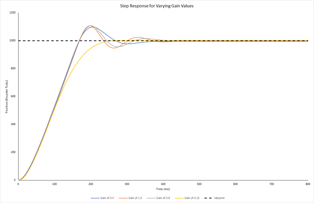
Having completed the Proportional motor control, the task was to implement a code in the main program that would call upon the previously made modules in order to power the motor and a duty cycle determined by the user's choice of gain. The motor is powered for 200 loops, while collecting time and positional data that will be used to generate a step response.
The goal here is to write a Python class encapsulating all of the functionality that will be useful for interacting with the motor and to write test code evaluating the functionality of the motor driver class. The motor driver class is able to control the speed of the motors by setting the duty cycle. The motor driver expansion board was carefully mated to the development board. The wire strippers were used to cut and strip back 4-5mm of insulation from the 12VDC power supply. The power supply was then connected to the screw termials labeled Vin and GND. Lastly the motors are connected to the screw terminals labeled A and B accordingly.
Equipment used:
The goal of the encoder driver is to measure where the encoder is at any particular time. The optical encoders used in this project are imbedded into the motors previously connected. The encoders take advantage of the timers included with the STM32 processors. The timers will read the pulses generated by the encoder and it will count distance and direction of motion. A pair of jumperwires were connected to the GND and 5V pins on the Nucleo and used to power the breadboard. Then the encoder channels A and B for the first motor were connected to pins PB6 and PB7 and the channels A and B for the second motor where connected to pins PC6 and PC7.
Addition Equipment used:
Please see encoder.Encoder which is part of the encoder package.
A motor with closed-loop control can be very fast, efficient, and accurate which is why we want to include it with our motors. The goal here is to create a class that will perform closed-loop proportional control. This class accepts a setpoint and a gain value, and a measured motor angle as inputs. Then, it takes the difference between the setpoint and the measured angle. This difference is the error and it is promptly multiplied by the gain and then used the the new duty cycle for the motor. Including this closed-loop proportional control greatly imporoves the motor's response to approaching the desired setpoint.
- Note: No additional equipment required for the proportional control.
An Inertial Measurement Unist (IMU) is a device that is used to determine the orientation of any physical object in which the device is attached to. The IMU used for this project is the Bosch BNO0559-axis IMU. This IMU is comprised of a 3-axis accelerometer, a 3-axis gyroscope, and a 3-axis magnetometer. The accelerometer measures linear acceleration in the x, y, and z directions. The gyroscope measures angular velocity about the x,y, and z directions. Finally, the magnetometer will measure the magnetic field strength inn the x,y, and z directions. The With the addition of the magnetometer sensor, the orientation of the object can be used to determine the heading, pitch, and the roll of the object.
❗ The following is a link to the respository where you will find the source codes: ❗
✔ https://bitbucket.org/jchave91/me405_lab/src/master/ ✔
Display of the IMU Euler Angles
This is a short video clip of the me running the IMU script in a while loop. The Euler angle are displayed every second for 200 passes through a short loop. In this video I use two protractors, one which is attached to the IMU and the other to my working table. I make sure the IMU is fully calibrated first and then line the imu at 0 degrees. I run the program and as it prints Euler angle values, I rotate the imu clock-wise to increase angle. I shortly stop at 90, 180, and 270 degrees to briefly display matching angles.
NOTE:
Holding the camera, running the program, and trying to rotate the imu was a small challenge. Apologies for the subpar view ❗